Sistema Autoalimentado
The main goal of the project is to achieve a non invasive solution for power consumption measurements in distribution panels. A self-powered device has been designed exploiting the magnetic field generated around the same power line whose monitoring is desired. Wireless technology will be used to transmit the data.
Finally, an energy management system and a data visualization system have been designed and developed.
1. MOTIVATION AND GOALS
Nowadays, power consumption metering devices installed in electric panels are, to a greater or lesser extent, invasive. This kind of problem is due to several reasons, such as the necessity of a power supply from the electric panel itself or even the use of transformers that change the electric installation schema.
This involves, in one way or another, that a switch off in the electric panel is necessary for the device's installation. Also additional wires can be needed for the power supply or the device communications.
The goal of this project is to offer a simple way of measuring the power consumption: a non-invasive and wireless way. Therefore, this avoids any kind of switch off or changes in the electric panel and also the installation of additional wires.
Equally important is the storage and visualization, in a simple way for the user, of the measured data.
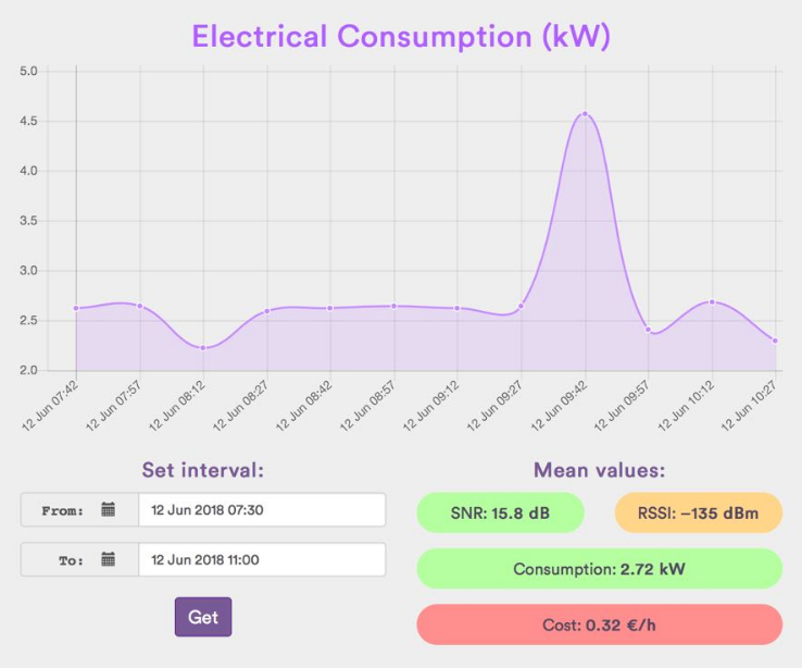
Illustration 1: Dashboard showing the energy consumption in an electric line.
2. SOLUTION
In order to fulfill the previous goals, a self-powered device has been proposed and designed. This has been achieved thanks to inductive techniques of Energy Harvesting, taking advantage of the magnetic fields that a conductor cable creates around itself, in order to supply power to the device.
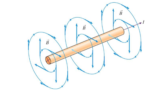
Illustration 2: Magnetic Field generated by a conductor cable.
Therefore, is not necessary to get the power supply from the electric panel. Instead, the power supply is harvested and stored in a small battery, whose target is to maintain the device's power supply in every moment.
This same conductor cable that supply the power is also the target of the energy measurements, so the designed device alternates between measuring and sending the energy consumption data, and the maintenance of the battery charge level.
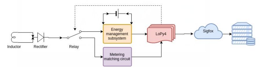
Illustration 3: General System Schema.
The limited quantity of available energy dictate the need of an extremely low power consumption in the microcontroller and the peripherals together with an intelligent energy management system.
The data is sent in a wireless way via Sigfox, an especially designed network for IoT devices with very low power consumption, low data rate and wide-area range.
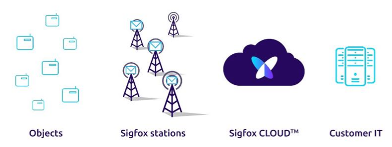
Illustration 4: Sigfox Network Schema.
The use of Sigfox eases the communication and the device control from every place through the Internet. Given the Sigfox wide geographic coverage in Western Europe (95% coverage in Spain), United States, Australia, New Zealand, South-Africa, Japan and large areas in South-America, devices can be installed nearly everywhere. Also, transmissions with Sigfox are characterized by its high energy efficiency.
In order to use Sigfox, the use of a compatible transceiver is necessary. A LoPy board has been used in this project because it fulfills all the previous requirements: low power modes, multiple general purpose inputs and outputs and a Sigfox-compatible transceiver.
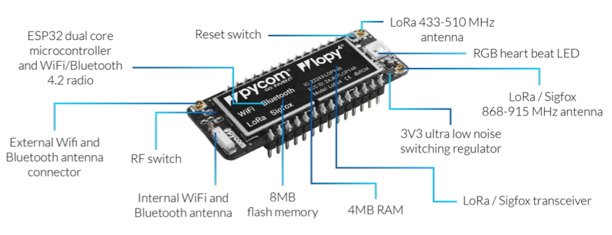
Illustration 5: LoPy4 Components.
A webserver has been developed for the visualization and storage modules. This webserver contains a RESTful API that can be accessed by external clients to use the data stored in a database. The components of this module use the following technologies: Node.js, Express and MongoDB as the database. The development of the RESTful API offers an abstraction layer that can be used by the final clients with multiple purposes. The Sigfox API works as an external client for this RESTful API, sending data via HTTP POST to the webserver while receiving the energy consumption measurements from the device. In this way, the measures are stored in the MongoDB database. Finally, a Web Client (with AngularJS) has been developed. This web client requests the energy measurements to the RESTful API, via HTTP GET, and then allows the visualization of the data through the creation of dashboards with the stored data. All this modules shape the MEAN stack (MongoDB, Express, AngularJS and Node.js).
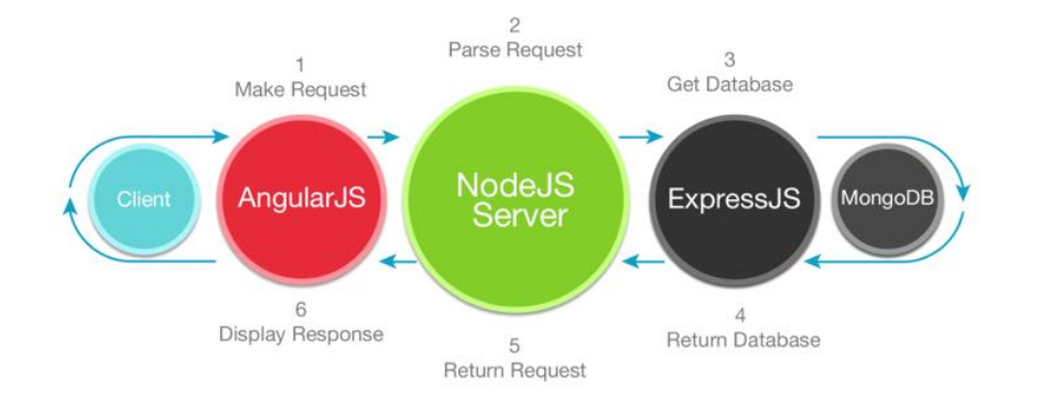
Illustration 6: MEAN Stack.
3. TEST AND RESULT VALIDATION
To achieve the goal of getting a functional prototype with the required characteristics, the next steps have been followed.
At first, a deep study about the Low Power Modes (LPM) of the microcontroller have been carried out in order to achieve the lowest power demand. This is crucial in the development of the project due to the inverse relationship between the power demand and the flexibility of the design process.
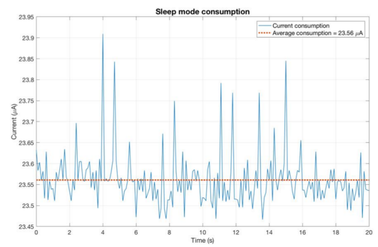
Illustration 7: LoPy4 energy consumption in low power mode
The processor switches between several power modes, some of them with higher and others with lower power consumptions. This happens because the energy harvested from magnetic fields induced on the power line is not enough to maintain continuously active all the microcontroller’s peripherals, so it is necessary to switch to a lower power consumption mode. Of course, microcontroller’s firmware must be designed to match the energy management system, making possible to change the wireless transmission periods and the power consumption measurements depending on the available energy.
Numerous measurements have been gathered to enlighten the relationship between the quantity of energy extracted of the magnetic field generated around the conductor and the current going through the power line.
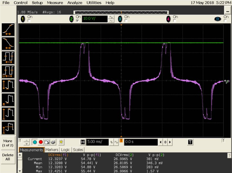
Illustration 8: Input signal from inductor (purple) and rectified signal after capacitor filter (green).
Once the viability of the project is ensured, the next step has been to develop the signal conditioning and the energy management systems to adapt the harvested energy to the microcontroller requirements. The energy management system is composed by a capacitor and a battery, making possible the distribution of the incoming energy in an efficient way.
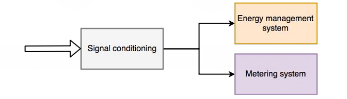
Illustration 9: Operating modes of the device.
At last, a firmware for the microcontroller has been developed to optimize the use of the available energy, as well as the data transmission protocol.
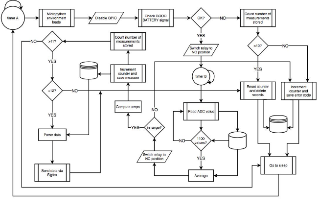
Illustration 10: Firmware flowchart
This firmware must fulfill the discussed restrictions, as well as fit the available resources at any time. Also, it must ensure that the stored energy is not below the minimum needed by the microprocessor to work, avoiding the risk of making the device inoperative.
4. CONCLUSION AND FUTURE SIGHTS
After passing all the previous tests, a new completely self-powered power consumption metering device has been installed in an electrical panel.
The main purpose, which is gathering the information about an electric line power consumption without changing the installations or adding wires, has been achieved.
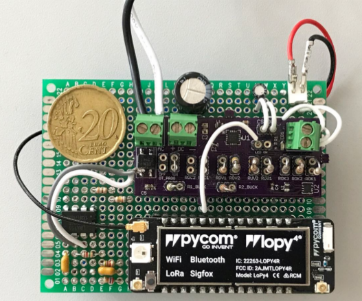
Illustration 11: device's top view, with LoPy4 and Energy Harvesting PCB.
The analysis of the stored measures has helped to save energy by giving a better knowledge about the consumption habits. At the same time, the device has helped to reduce the pollution.
However, the prototype can still be improved. For example, by performing the same job over three-phase consumption lines or over several single-phase lines. This would imply the implementation of a more complex circuit, although increasing the number of inductors also implies a higher quantity of harvested energy and therefore, the possibility of increasing the quantity of transmissions.
The device could also change the frequency of transmissions dynamically depending on the level of battery charge.
In addition to this, a short-term change would be the reduction of the device size by using surface mounted components instead of through hole ones.
Furthermore, the LoPy4 board could also be changed to a more professional version, due to the fact that the one used in the project is a development one. Another future step could be the design of a board with a new Sigfox-compatible microcontroller which would also integrate the whole power-supply module.
The reduction of the size of the battery is also possible because it has turned out to be over-sized for the project. Also the antenna could be reduced changing it for a new, more integrated, one.
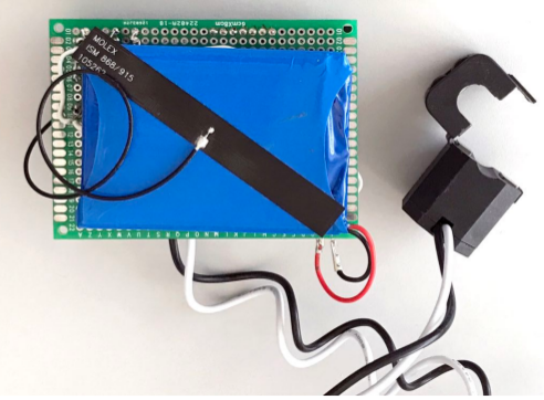
Illustration 12: Device's bottom view, with battery and current probe.
Different techniques such as RF wave induction harvesting or solar energy harvesting could be implemented in other scenarios.
To conclude the description of this project from a software perspective, it could be interesting to apply Machine-Learning algorithms with the reduction of power consumption as the main target. Even more, this algorithms could predict failures in the power line based on daily consumption patterns.
